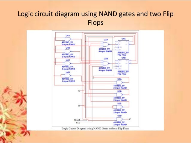

e completed design will be simulated in Verilog and tested by programming the Spartan 3E FPGA 1 Vending-Machine Controller ENEE 245: Digital Circuits and Systems Laboratory Lab 9ĮNEE 245: Digital Circuits & Systems Lab Lab 9 A Block Diagram of Hardware for a Finite State Machine Vending Machine Controller Specification is lab involves the design, simulation and prototyping of a vending machine controller. A combinational logic block called Next State Logic takes the state information and the system inputs as inputs and determines the next state of the circuit. At the hardware level, the FSM state is kept track using a collection of flip-flops that are driven by the same clock signal (forming a synchronous sequential circuit).

FSMs are very widely used in digital system designs. Finite State Machine (FSM) A finite state machine (FSM) is an abstract description of a digital circuit in terms of (i) a collection of states and (ii) the transitions that allow the circuit to go from one state to another, based on the current input values. A user will input a product code via a keyboard interfaced with the FPGA and the system will dispense the corresponding product and change, if the price of the entered product is less than or equal to amount deposited by the user. e payment, dispensing, and returning change will be simulated by using the switches, buttons, and LEDs of the Nexys2 board. is lab involves the design and implementation of a vending machine controller.

simulation takes double clock pulse for output.(when i put 25 ps 8 times or 8 clock pulses is required for getting output. If more than 1rs is inserted, the balance will be returned. I have written a verilog code for a simple coffee vending machine with inputs


 0 kommentar(er)
